
Following GCL installation from roll deployment to seam closure
Geosynthetic clay liner arrives on site in rolls. Panels are unrolled to the layout and connected through overlaps to form the lining. These field photographs follow roll deployment, panel positioning and bentonite placement at an open seam. Read together, they connect the handling of a roll with the preparation of the joint between adjacent panels.
Position the panels before preparing their overlaps
During deployment, the crew positions the panel along its planned direction and lets it rest against the subgrade. Once the main panel is in position, the adjacent edges can be aligned. Resolving folds and bridging at this stage reduces the need to move a panel after its seam has been prepared.
A side overlap follows the long edge of the roll; an end overlap connects successive panel lengths. Mark their dimensions and treatment separately on the layout. Panel corners, seam intersections and cuts near structures also need to be considered while the panels are being positioned.
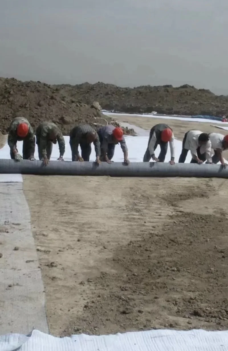
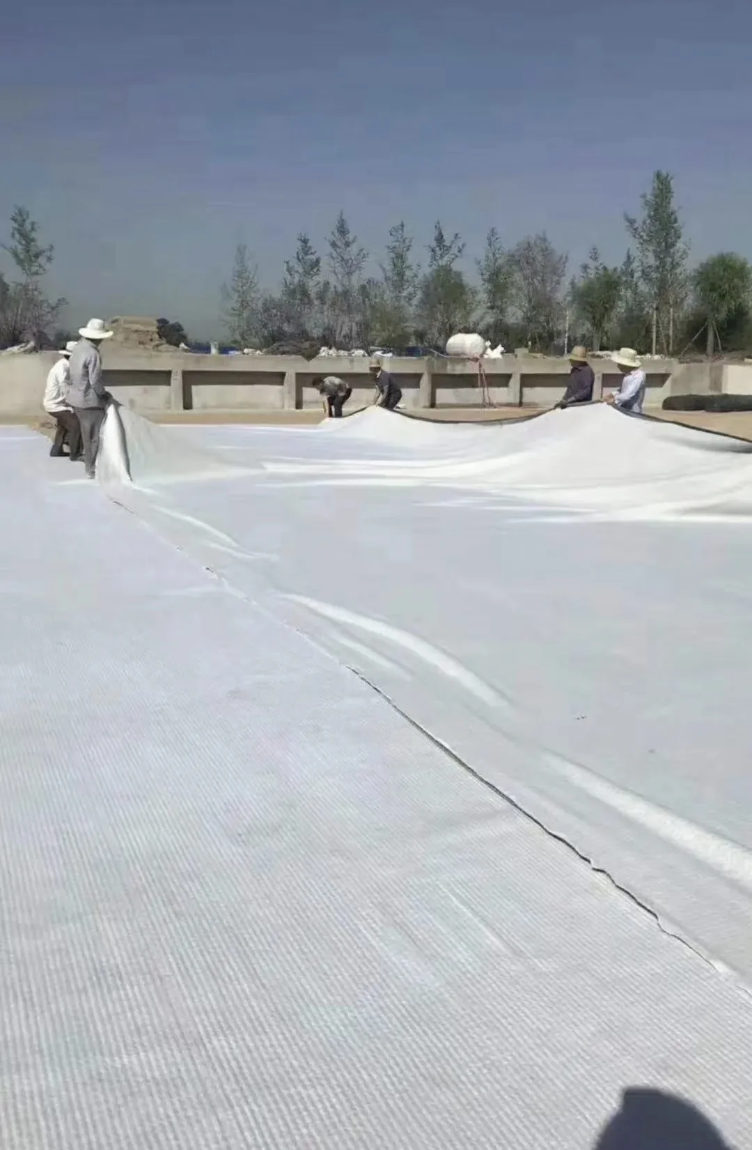
Apply bentonite where the joint detail requires it
One photograph shows bentonite being placed along an open overlap; the close view shows the lifted panel edge. The open joint leaves access for cleaning the contact area and placing the bentonite treatment. After the upper panel is returned to position, check the alignment and continuity along the seam.
Seam treatment needs to suit the selected GCL product. During procurement or installation preparation, define the accessory bentonite, application rate, placement position and end-joint treatment in the detail. This also helps the site prepare the required accessories. At intersections and corners, review the treatment together with the order in which the panels overlap.
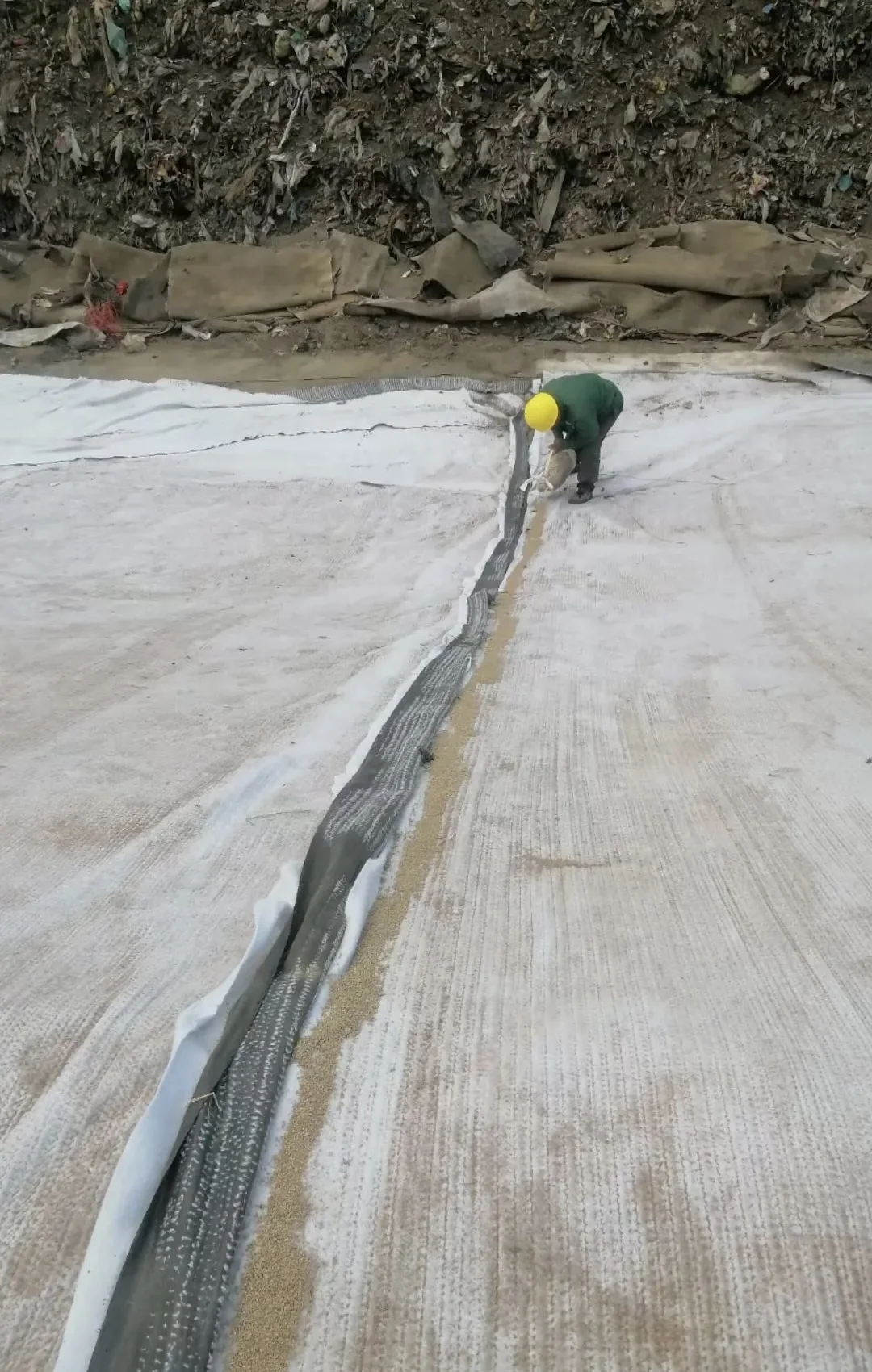
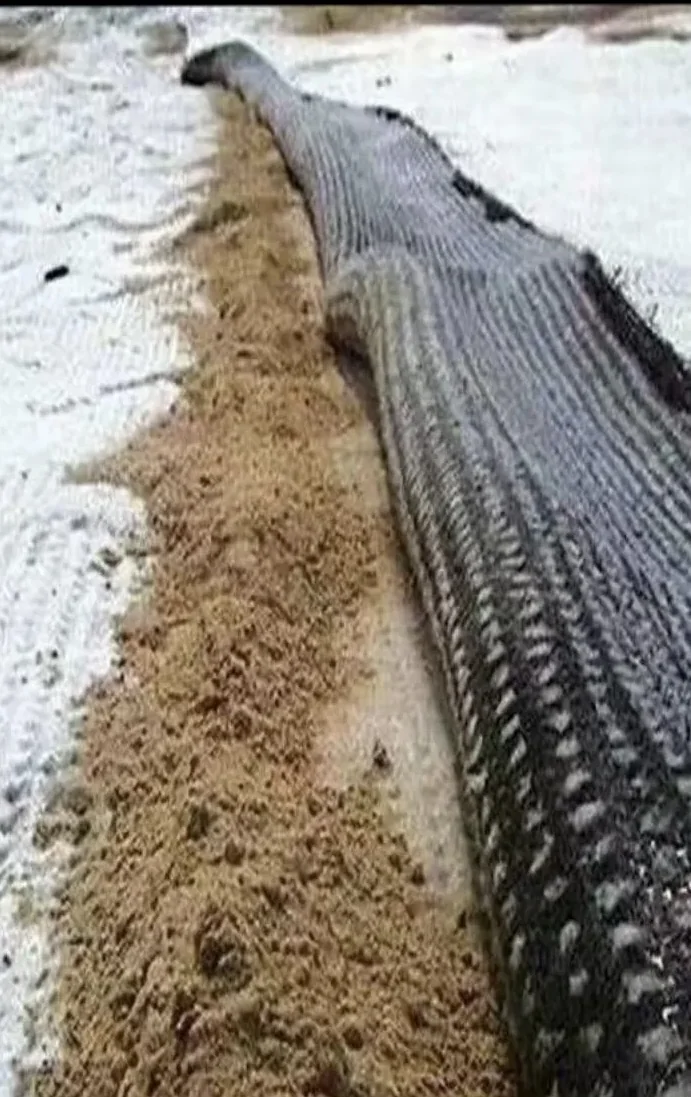
Connect the seam inspection with cover placement
Before covering, panels and details remain accessible. Check their position, the overlap contact areas and the structure connections while local damage can still be addressed directly. Match the inspection area to the area being prepared for cover. This helps limit further exposure and disturbance of completed work.
- Review the layout, panel positions and contact with the subgrade.
- Check side overlaps, end overlaps and bentonite treatment separately.
- Inspect corners, intersections, structure connections and repairs.
- Confirm the cover material, thickness and equipment access route.
Keep panels and seams in position during cover placement, and keep soil out of unfinished overlaps. Review equipment routes together with the cover plan so inspected areas can move into the covering operation.
Continue with the artificial lake supply projects
The Baiyun District project in Guangzhou shows delivered rolls, field sampling and testing equipment. The Guang'an project brings basin lining, a concrete structure detail and night-time cover placement into the same set of site views. Read both cases alongside the overlap diagram and detailed steps in this guide.
Install GCL as a continuous barrier: prepare the ground, place relaxed panels, close and treat the joints, inspect, then add the specified cover. For VABREN GCL-NP, mark side and end overlaps separately. An open or contaminated joint must be corrected before it disappears under cover.
How to form GCL side and end overlaps
The side joint follows the roll length; the end joint connects two lengths. On the layout, give each its own width, lap direction and treatment. Do not use a single overlap value for both without the selected liner detail.
- Mark the lower panel. Identify the side lap S and end lap E. Keep the contact zone free of loose soil and debris.
- Place the upper panel. Follow the runoff direction shown on the layout. Keep the liner against the surface without stretching it across hollows.
- Treat and measure. Apply the specified joint material, then check the continuous overlap at corners and intersections as well as straight runs.
- Hold open joints. Correct displaced edges, contamination and unfinished penetrations before release for cover.
The required dimensions depend on liner construction, hydraulic conditions, ground movement and the project detail. GCL-NP material test results do not prescribe installation widths. Ask for the side and end details before cutting panels; do not infer them from roll weight or a quantity example.
Does a GCL overlap need supplemental bentonite?
Check the selected liner's seam detail. A bentonite-filled core does not confirm that an untreated side or end lap is acceptable. Where supplemental bentonite is required, keep it continuous in the designated position and apply the specified rate. Check intersections and penetrations separately.
Record the panel IDs, treated seam length and material used. A rate in kg/m applies to the seam length; the core's bentonite mass per square metre is a different measurement. Soil in the lap cannot replace the joint material, and a wider lap cannot replace a required treatment.
GCL installation sequence before covering
- Delivery and storage. Match roll IDs to the selected grade. Inspect wrapping, wet patches and handling damage; protect staged rolls from weather.
- Ground preparation. Provide a stable, smooth surface. Remove sharp debris, resolve standing water and mark panel positions, anchors and penetrations.
- Deployment. Use suitable lifting equipment. Avoid dragging the liner over rough ground; leave panels relaxed against the surface.
- Joints and details. Close the laps, apply the required seam treatment and complete cuts, structures and repairs.
- Inspection and cover. Release only the area ready to receive the specified cover. Keep plant on the protected working surface and prevent spreading from pushing panels or opening joints.
Can wet GCL be dried and used after rain?
Drying alone cannot show that the bentonite, reinforcement and seams remain serviceable. Hold the affected area before cover and inspect it. The decision may be retention, testing, repair or replacement; visible wetting by itself does not determine which.
- Protect and stop. Stop exposing more material, protect dry stock and keep traffic off softened liner.
- Identify the exposure. Photograph panel IDs, open joints, standing water and displaced areas. Note the exposure time and whether the liner was confined.
- Inspect the material. Check for separated geotextiles, tears, bentonite loss or migration, wrinkles and movement at penetrations.
- Close out the decision. Give the record to the responsible engineer or inspector and supplier. Record the agreed action and check repairs before release.
Mark the panel and hold cover placement. Check how far the lap moved, whether soil entered and whether bentonite was lost. Cleaning and repositioning may be part of a repair, but do not close the inspection until the material condition and seam treatment have been checked. This is an inspection example, not a completed VABREN field case.
How to allow for GCL overlap in a roll quantity
In a repeating panel grid, the interior coverage increment is approximately (W − S) × (L − E). W and L are roll dimensions; S and E are side and end laps. Boundary panels have fewer shared joints.
Calculation example: assumed W = 5.8 m, L = 30 m, S = 0.30 m and E = 0.60 m give 5.5 m × 29.4 m = 161.7 m², versus 174 m² gross roll area. These assumed laps are not GCL-NP installation dimensions. Add anchors, actual slope lengths, structures, repairs and cutting allowances to the final layout.
GCL inspection checklist before cover
- Product grade, roll IDs and panel layout are matched.
- Ground, side and end laps, seam treatment and intersections are checked.
- Penetrations, anchors and repairs match the installation detail.
- Weather exposure and wet-area decisions are closed out.
- Release, cover specification and placement times are recorded.
Download the GCL panel inspection record (CSV)
Choose the GCL grade and prepare your inquiry
Review the VABREN geosynthetic clay liner product and technical specifications and download the GCL specification reference (English PDF). The table compares GCL-NP, GCL-OF and GCL-AH requirements from the supplied schedule labelled JG/T 193-2006. Request current inspection documents for the selected grade; requirement values are not batch test results.
- Quantity: total m² or roll count; state whether overlap and cutting allowances are included.
- Application: lining purpose, liquid or water conditions, slope, cover and relevant drawings.
- Destination: country and port or delivery location.
- Project specification: model and construction, total and bentonite mass, roll dimensions, required properties and test methods. Include proposed side and end overlaps for installation review.
If drawings or specifications need to be sent separately, email info@vabren.com with the same project name used in your inquiry.
Request a GCL specification and quotationView GCL production